Launch the Signal Studio software.
This ensures that all settings are set to default values.
If there is a need to configure the instrument settings different from the default, click the Instrument node and configure the settings for each section, as required.
For more information, refer to the Instrument node topic.
Click the Waveform Setup node and configure its settings:
-
Click Custom Modulation and use the drop-down menu to view the available choices.
-
Select Custom OFDM (the default selection).
-
View the settings in the Basic section and notice that the number of frames and oversampling values are editable.
-
When finished viewing, ensure that the Number of Frames and Oversampling Ratio values are the default values of 1 and 4 respectively.
-
If there is a need to change the default marker signal selection, click or and change the selection.
For more information on markers and their settings, see the Waveform Setup topic.
Click the Custom OFDM node and configure its settings.
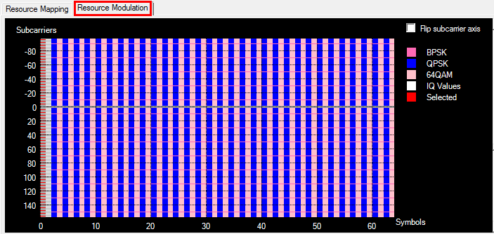
For more information on these settings, refer to the Custom OFDM topic. Use the graphs at the bottom to monitor changes. The graphs in this window are the same graphs shown in the Resource Mapping node and reflect changes from both nodes. At this point, both graphs reflect default settings and should look similar the ones shown below.
-
Set the Idle Interval to 10 us.
-
Enter an FFT Length value of 512.
This cell value is coupled with the Guard Lower Subcarriers and Guard Upper Subcarriers cells. The length must be sufficient for the required subcarriers.
-
Click
 in Cyclic Prefix Length to open an editor window. Do not change any values for this example.
 -
Click in the Guard Lower Subcarriers and set its value to 79 Subcarriers.
-
Click in the Guard Upper Subcarriers and set its value to 78 Subcarriers.
-
For this example, leave the remaining settings at their default values.
Click the Resource Mapping node.
Within this  view, each resource block (RB) is configurable. In addition, tools just above the list provide the ability to Add, Remove, Copy, change an RB list position, and change the constellation. For Information on these tools and any of the settings in this window, see the Resource Mapping topic. Use the graphs at the bottom to monitor changes.
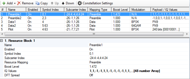
Configure the resource blocks:
-
Click 1 (Resource Block 1) in the # column or any where in this row to enable changing its RB values.
-
In the settings window below the RB list, configure the values according to the table shown below.
-
Repeat these steps for each subsequent RB row.
RB 3 and 5 are being reconfigured as a different Resource Mapping type.
|
|
Preamble 1 |
Preamble 2 |
Data 1 |
Data 2 |
Pilot |
|---|---|---|---|---|---|
|
Name |
Preamble 1 |
Preamble 2 |
Pilot |
Data_QPSK |
Data_64QAM |
|
Enabled |
On |
On |
On |
On |
On |
|
Symbol Index |
0 |
1 |
2:63 |
2:2:63 |
3:2:63 |
|
Subcarrier |
-176:4:-4,4:4:176 |
-176:2:-2,2:2:176 |
-150:20:-10,10:20:150 |
-177:-2,2:177 |
-177:-2,2:177 |
|
Resource |
Preamble |
Preamble |
Pilot |
Data |
Data |
|
Boost Level |
1.000 |
1.000 |
1.000 |
1.000 |
1.000 |
|
IQ Values1 |
Zadoff-Chu |
Zadoff-Chu |
--- |
--- |
--- |
|
Pilot Data Mode |
--- |
--- |
Payload Bit |
--- |
--- |
|
Resource |
--- |
--- |
BPSK |
QPSK |
64QAM |
|
Modulation |
--- |
--- |
0 |
0 |
0 |
|
Payload2 |
--- |
--- |
Custom |
PN9 |
PN9 |
|
DFT Spread |
Off |
Off |
Off |
Off |
Off |
|
Multiple Access Scheme |
--- |
--- |
--- |
Off |
Off |
1. To set the values, click in the cell and then the dialog box icon to launch the IQ Values dialog box. For this example, click Preset > Zadoff-Chu. The values shown in the table are examples of the some of the values from the dialog box.
2. To set the values, click in the cell and then the dialog box icon to launch the Data Setup dialog box. Then set the payload.
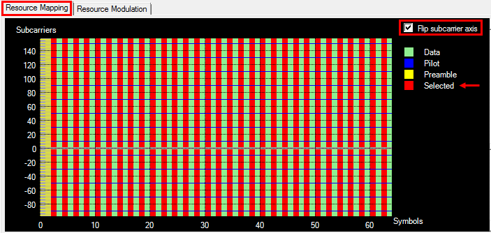
Select row 1 (Preamble1) in the resource block editing table. The Resource Mapping and Resource Modulation graphs reflect your changes and should now look similar to the ones shown below.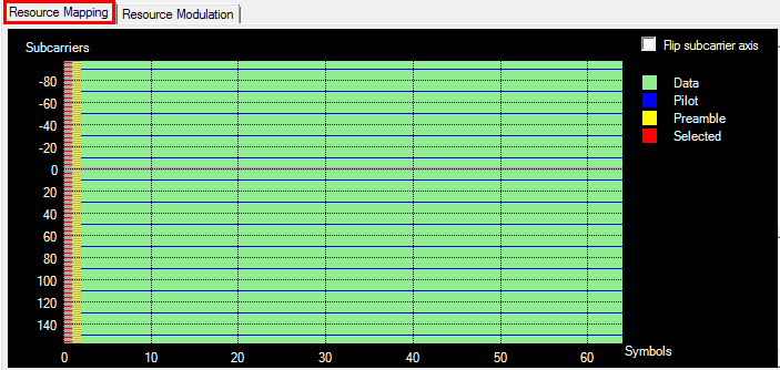
Click in the Resource Mapping graph. Notice the change in Subcarriers axis.
Now click row 4 (Data_QPSK) in the resource block editing table. Notice the "Selected" (red) areas switch to highlight the QPSK data mapping, as shown below.
Click the Download icon in the toolbar to generate and download the waveform to the instrument.